Andy's Fine Woodworking
  • Home
  • Portfolio
    • Tables
    • Coffee Tables
    • Beds
    • Benches
    • Boxes
    • Cabinets
    • Chairs
    • Doors
    • Ladders
    • Remodels
    • Misc Projects
  • Inventory
  • Process
  • Art Tours
    • Open Studio Art Tour
  • Contact
    • Bio >
      • Links
  • Stilts

Complex Projects and the Details Behind them

REdwood Slab Bed

10/8/2016

3 Comments

 
Picture
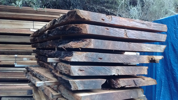
This is where I stepped into the project. The Clients cut up an old redwood tree that fell across their driveway. They had it cut into 8.5foot sections and then kept the lowest cut for themselves. They had that log stored in a slab yard in Ben Lomond to dry for a year. Then the contractor, Tony, and I heaved the slabs around, sorting out the ones which were ours and drove them back to my shop for an initial milling.

Picture
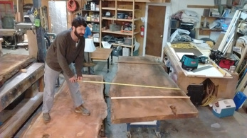
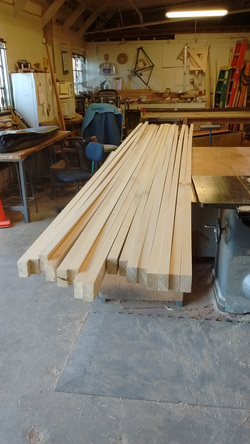
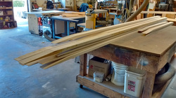
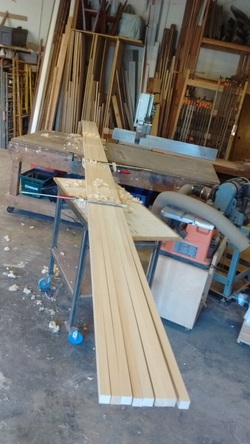
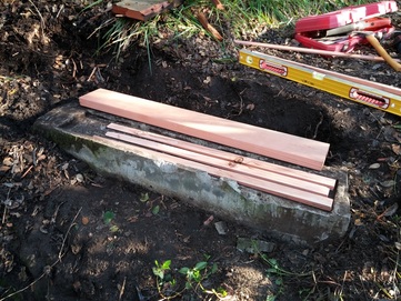
Here you can see Tony measuring slabs. We picked the best 5 slabs and then used his big foot circular saw and cut up the rest of the slabs for bed frame, drawer and side table parts.
The slabs then took a ride with Tony to the kiln in Watsonville and underwent two drying rounds. They were brought back to my shop but before the real work began I did something else.

Picture
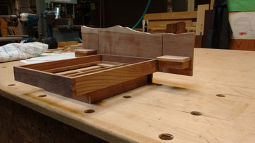
I made a 1/8th scale model to get all the design details right. It worked and it was so cool the clients wanted the model when the bed was completed.

Picture
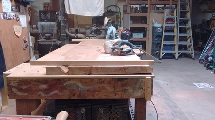
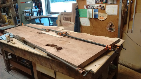
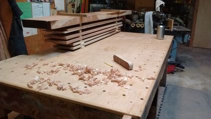
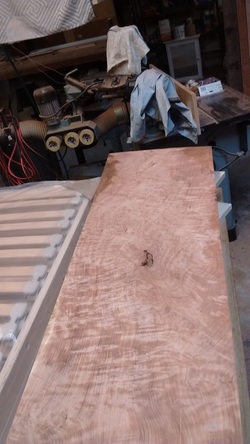
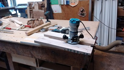
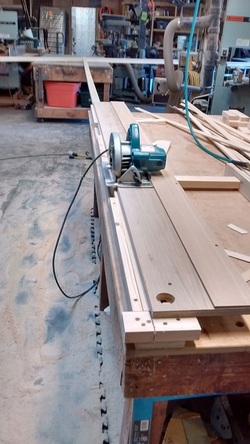
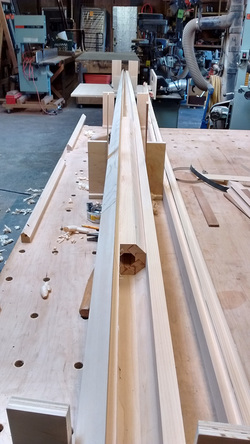
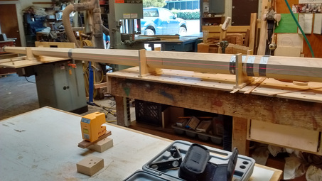
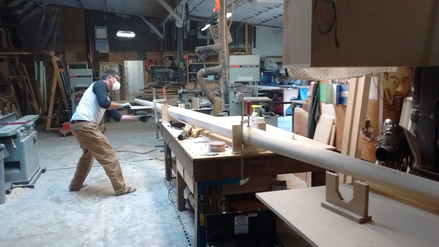
The slabs were sorted and cut to rough length. Then they were flattened with an electric hand planer. I used age old techniques in this process because the slabs were simply too large to do anything else. I used twining sticks to get the twist out of the slabs. The photo to the left shows this step with the twining stick and the electric planer on top of the slab. If you look closely you can see how much twist there was in the slabs by looking at the right bottom of the closest edge. The black space between the table and the slab gives you a good idea.

Picture
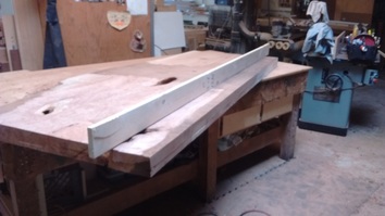
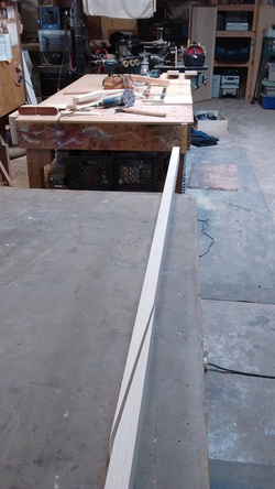
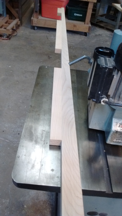
I then planed them flat across the length using a flat board on edge. I worked only one side of the slab because the second side would be taken care of with the time saver. Here you can see the board used to flatten the slab lengthwise.

Picture
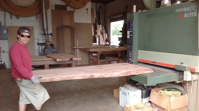
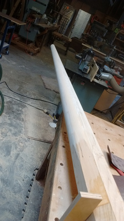
The time saver is a large belt sander that can flatten any wood item really fast, hence the name. I placed the slabs flat side down and the belts flattened the second side for me. Then we cleaned up the side I flattened and Vwala the slabs were flat and sanded mostly clean.

Picture
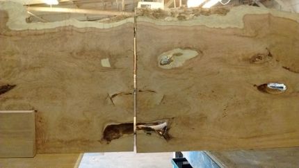
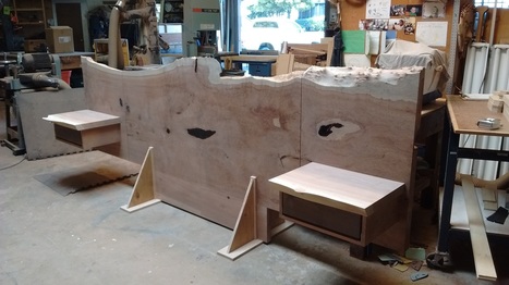
To achieve what the clients wanted in the design we had to make 8.5ft slabs turn into 10.5ft slabs. I managed this by taking the slabs from above and below our chosen slab and flipping them over end for end. I cut them down and attached them to the ends of the best slab. This is called book-matching but is rarely done this way with slabs. The result was pretty awesome accept for one thing. We created a scary jack-o-lantern face that I could not leave as it was. I fretted over this issue for almost a month.

Picture
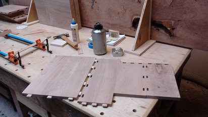
Here is how I attached the slabs to each other. I used many large 5" dominoes creating an industrial strength joint.

Picture
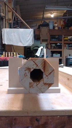
Here you can see I have joined side two creating the Jack-o-lantern face.

Picture
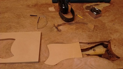
My solution to the jack-o-lantern face? Get rid of the mouth. The mouth was two large holes in the slab combining into a wicked grin. I grabbed my balls and made a patch, routed it out and filled it with similarly active material. To the left you can see the template I made and the patch which fit into it.

Picture
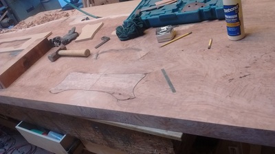
The patch was successful but still looked a little obvious to me. But once I planed it flat and sanded everything it mostly disappeared. I asked the finisher if he could find it and he couldn't so I felt better about that. It also ended up mostly covered by one of the side tables so it was fine.

Picture
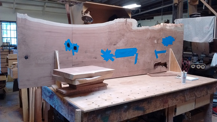
I had to do a lot of epoxy work to fill all the holes and voids in the slab. I finally figured out the best way to do it by the time I was done. Cover A face with blue tape. Flip slab. Fill hole from the back (B Face). Once dry, flip back, peal off tape and lightly sand. It took me a long time to figure this out. The result; no bubbles, perfectly flat, very little work for a nice final finish.

Picture
Even though I kept the wood stacked and stickered a few hot days created enough movement that I had to redo some of the flattening. 

Picture
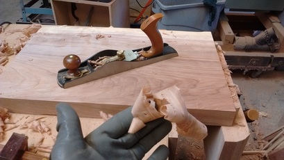
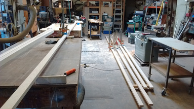
The smaller slabs for the floating side tables were still too large for me to run through my machinery. So again I had to break out the planer, the jack planer this time, and flatten the slabs with sweat and hard work. Both side had to be done this time, Ugh.

Picture
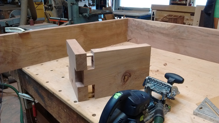
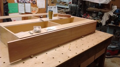
Building the parts for the drawer boxes. I wanted to make them strong, to last, so I built them well and sturdy.

Picture
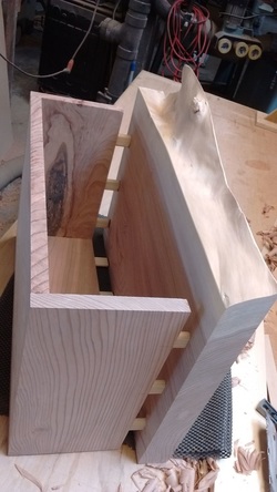
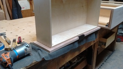
Here you can see the side table box almost complete

Picture
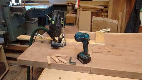
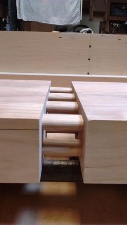
To attach the floating side tables to the slab I had to cut dominoes out in the plain of the slab face. This was a little challenging but with the right jig and the right mind set it came together quickly. It was a little hard to see so I shined some light on the setup.

Picture
Here is the attachment of the side table. Strong. I also put 4 seven inch lags through the slab into the back end of the top of the side table.

Picture
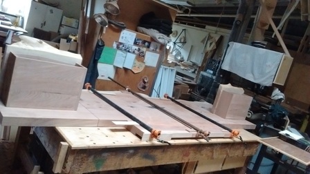
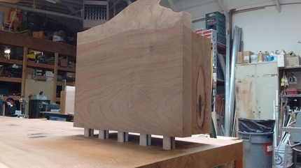
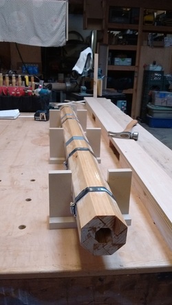
Once the side tables were in place I had to glue the foot on with dominoes in the same way I jointed the slabs together.

Picture
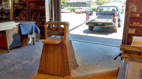
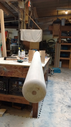
Here is the slab standing up on its foot with brackets to hold it up vertically.

Picture
After the headboard was complete I began work on the bed frame. The material I had to start with was amazing. Lots of curly ribboned action.

Picture
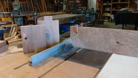
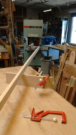
We decided that the corners of the bed frame would have a beefy box joint. Once my parts were milled to size I cut the box joint on the table saw with success.

Picture
Here is the vertical step of cutting the giant box joint. That jig and clamp were essential.

Picture
I had to do several test runs with blocks of scraps to get the joint really dialed in. The result was another awesome sample. This picture does a good job if capturing the domino tool in the foreground, the sample joint in the midground and the real joint in the background.

Picture
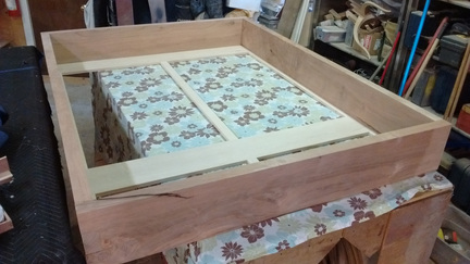
Here is the Bed Frame with maple support structure underneath. There was going to be a slat system to hold the mattress and this needed support within the bed frame. Also the bed frame was going to sit atop a drawer box frame but the front end of the bed was going to be floating out 18 inches. Hence the maple support near the end.

Picture
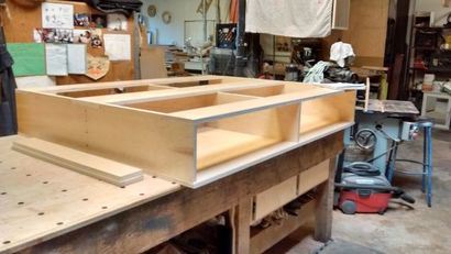
This is the cabinet carcass that will house the 4 large drawers that pull out from under the bed.

Picture
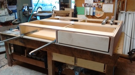
Here is the cabinet carcass with the fancy drawer slides and drawer boxes.

Picture
Since I had plenty of redwood I chose to use a continuous Board for the drawer Fronts on each side. Here you can see the setup and the spacers under the drawer face.

Picture
Once the drawer faces were attached I installed fancy minimalist drawer pulls which were specified by Tony. They looked really good but mostly disappeared under the bed.

Once all the parts were constructed I laid them all out on the floor of my shop and bolted them together. The headboard and the bed frame were bolted together with 1/2" nuts and bolts through the slab headboard and through the 2" bed frame board. The bed frame was screwed down into the drawer box through the maple supports. The assembly was checked and then taken apart.
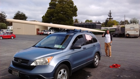
The parts were delivered to the finisher in my truck. I was greatly relieved to be rid of the project as it was becoming all consuming. I was also several thousand dollars over budget so seeing it depart was a great relief.
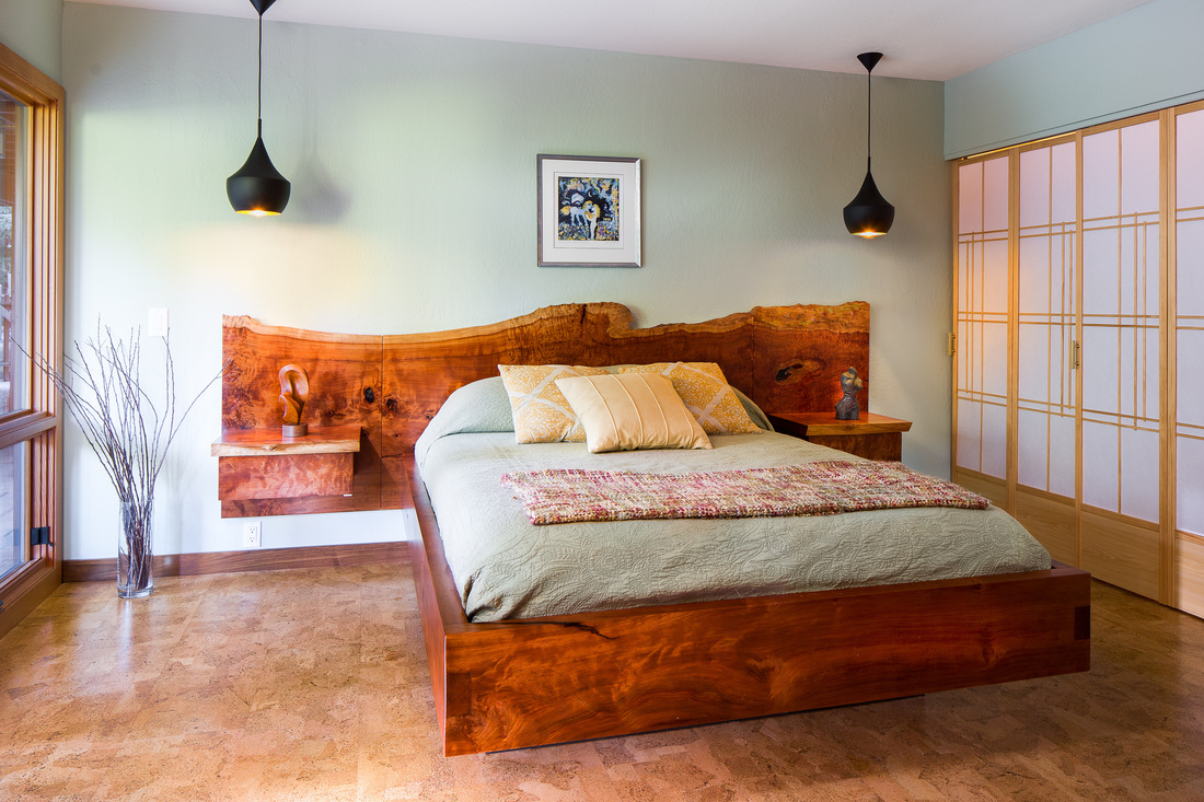
The Finisher was really good at what he does. The bed was finished in a timely manner and then delivered to the client. There was some post delivery electrical work to be done by Tony. Finally a photographer was called in to take pictures and Vwala, here is the image of the log become a bed.
Picture
3 Comments

Tapered Octagonal Spar for Abraham

9/18/2016

1 Comment

 
Picture
I did a lot of research online before I tackled this project. There is a wealth of information on building octagonal spars and other blogs and videos on using a birds-mouth cutter. The only thing I did not find was a spar that was tapered on both ends. I found a few projects where the pole was tapered in one direction so there was no reason to believe that it could not be done to both ends. 
I chose Port Orford Cedar because it was cited on a few blogs as an excellent material for Spars. Unfortunately what I was able to find was fairly new growth so I was careful in my design and construction of the project to ensure maximum strength.
In the photo you can see the initial milling of the Port Orford Cedar into individual staves. The size is rough and the length on my starting material was 14ft.

Picture
I needed to build a spar roughly 22ft long so I had to make many long scarf joints to get the length I was looking for. The Photo on the right shows my initial rough Cutting of the 12" long Scarf joints. I laid out the cut and then quickly sliced through the material with the band saw. Later in the process I trimmed the scarf joint clean and crisp for maximum face grain glue up.

Picture
Here you can see the rough Scarf joint cut on all the boards. This step did not take very long. It was important to lay out all the cuts on the whole spar before hand to make sure all the joints are well staggered.

Picture
On the right you can see the jig I constructed to perform the finish cut of the scarf joint using a router for a perfectly smooth face for gluing. The initial set up was time consuming but I could perform the cleaning of each joint in about 5 to 10 min. The only issue I had here was when the end of the board would peal up from the bottom as I milled down to the last 32nd of an inch. Thankfully I milled all my material an 1/8th to 3/16ths oversized to account for these kinds of issues.

Picture
Here you can see an example of a clean and crisp scarf Joint which is 12" long. This was in preparation for the glue up.

Picture
I used west systems epoxy to glue all the scarf joints. This allowed for a long open time and resulted in a massively strong scarf joint. On the right you can see the gluing and clamping of 5 out of 10 scarf joints.

Picture
Once the scarf joints were glued and cured, I proceeded to mill them down to final thickness and width. This posed a challenge because working with 22' long staves was a first for me. They were so long I had to use the "Tailgate Infeed" from my truck into the planer and out the other end way into the shop. It worked though, and I had nice crisp, clean joints after the milling removed all of the imperfections from my jig setup.

Picture
The next step was to taper both sides of each end of each stave. I needed to remove only 7/16th of an inch on either side. This definitely required a jig. Here you can see the setup, tapering with a skill saw. This proved to be quite accurate compared to several other techniques I was considering. I had to taper each piece 4 times. With 8 staves that ended up being 32 tapers. Ugh. I had some problems at the beginning due to the fact that my skill saw was out of square and cutting an angled taper. PROBLEM! I fixed it eventually but this resulted in issues that showed up in the final glue up preparation.

Picture
I was concerned with the transition from straight octagon to tapered octagon. So after the tapering process I clamped all the staves together and eased the transition from straight to tapered using my hand plane. I took off a lot of shavings but in the end I think this step was superfluous because the taper was so gradual. 

Picture
Cutting the birds mouth on the shaper with a 45 degree bit was more of a challenge due to the fact that the tapered ends were so small. They were rolling into the shaper bit instead of staying flat on the table. I solved this issue by screwing blocks of cedar to the sides of the staves and then running them through the shaper feeder this way. This worked but resulted in screw holes that showed up when I started to round the tapered ends of the spar. Ugh. They mostly disappeared and were not that structurally important as they were filled with epoxy in the glue up process. They just looked unsightly.

Picture
I was initially going to build a solid core for the straight portion of the spar but the amount of material needed would have added a great deal to the weight of the spar as a whole. So instead I decided to mill the parts for an interior octagon to fill the central portion of the spar and add strength. On the left you can see the Octagon Core. This was extremely helpful in that it gave me a practice round in preparation for the major glue up of the entire spar. It also showed me that there were some cumulative errors that made the parts not fit perfectly together. As if some of the cuts were not correct, resulting in a slight gap. That was OK due to the thick and gloppy nature of the epoxy. Still it encouraged me to buy a filler for the epoxy that effectively turned it into peanut butter. Perfect!

Picture
The Birds Mouth seen from the end, lovely. If you can't see the imperfection I will point it out. The top right joint is slightly open but all the other joints are nice and tight. I think I will have to find out why that occurred the next time I use this bit.

Picture
The picture on the left shows the preparation for the glue-up. It was well worth going through the process. It showed that the cumulative error was great enough that I had to do something about it. I believe that part of the cause was the slight angle cut into the tapers on the first few rounds of cutting the taper with my skill saw. I removed the staves and hand planed all the stave sides square. Then I reassembled the whole spar a second time and found significant improvement. But it still wasn't perfect. Why, I do not know for sure, but it was close enough to call it good. A 1/32nd gap on two joints was not going to ruin the spar, especially with the type of epoxy I was using.

Picture
I wanted to make sure that the spar was glued up perfectly straight so I set up my laser to make sure. Again this was in preparation for the glue up.

Picture
My friend Carlos came over to help with the glue up and it went very smoothly. I did have to clamp with hand clamps and then tighten the hose clamps in a slow methodical process all the way down the spar. But I had time and the end result was a great glue up. In the picture you can see that it was "Totally Clamped Dude!"

Picture
The client, who is pictured to the right decided that he wanted the ends rounded but the central portion left octagonal. This made it easier but the rounding of the ends was still pretty challenging. I did not take it very seriously and the result was something that looked nice and round but in reality was not. I made a small hand tool to show me where to cut another facet in the octagon. I made the tool in a sloppy fashion and then used it in a sloppy fashion. Here I am admitting to all my mistakes. That is OK because really, I kick butt! I used my electric hand planer and cut down the high point and effectively made 16 facets on the rounded ends. Then I cut the next high point and made 32 facets on each end. At this point it was time to sand so I purchased several sanding belts and did what the client is doing here for about 3 hours. Talk about a core workout. It kicked MY butt. So I asked the client if he wanted to get a good core workout. He was excited about it so he went to work for about an hour, sanding the 32 facets round. It looked great when we were done but I knew that it was not perfectly round. I will have to think of a more accurate solution next time.

Picture
Here you can see one end tapered and rounded. Looks nice doesn't it?

Picture
The mahogany plug at the end of the spar was a royal pain in the arse to make. I spent almost 4 hours trying to figure it out. I eventually did but I had to repeat the process 5 times to get it right. I had to mill a perfect tapering octagon that stuck out of the end just an inch or two. Here you can see the end of pole with mahogany plug. It looks great. It better!

Picture
The client was happy with the final delivery of the Spar. I think that I made exactly what he had in mind. It cost a little more than we initially estimated but the result speaks for itself. A 22ft long tapered octagonal spar!

1 Comment

Archery Bridge

2/7/2015

1 Comment

 
Picture
The old bridge was very bouncy. After an initial assessment, where I took off key deck boards, it was clear that both support beams were rotted out as well as broken in two separate locations.
Initially the discussion revolved around "sister"ing or replacing just one or two of the rotted beams.
After the assessment it became clear that all the supports would need to be replaced. So we tore down the whole bridge.
It was evident after this assessment that the handrail was holding up the bridge under compression.
It was clear from the severe rot on the support beams that it was time to replace the entire bridge. The supports for the old bridge were sistered 2x8 redwood beams. This technique has a tendency to collect water in the crevice on the top of the beams and rot them out from above.
Picture
Picture

After cutting up the old bridge I did an assessment of two landing sights for the old bridge. The wall closer to the classroom was very solid and didn't need any shim work. The platform on the archery side was tilted enough that it was necessary to create uniforms shims on the table saw to compensate for the tilt of the platform. Hopefully the weight of the new bridge will not tilt the platform more. It might be necessary at a later date to add more cement to stop this one from sinking.
Here you can see the two main support beams in place. After several discussions with Bear who seems to know everything, I changed my mind to some degree. I consulted an engineer through Paul who said that redwood is not strong enough to span the 19ft required. At first I purchased 4x8s in clear Douglas fir. I discussed the questions of rot with Jody and she flatly stated "No Pressure Treated". So my options were only one; Construction grade Douglas Fir. So I chose to go really beefy at 4x12x20ft. That way if rot develops, it will take a long time to eat enough of the beam away to compromise the bridge. Second the beams will be painted with primer and paint to protect them.
Finally the beams were capped with redwood ends, wrapped in protectowrap where they connect, and both beams were bolted down with all thread and epoxied into the cement walls
Picture
Picture
The next area of potential rot is the tops of the beams. Especially where the redwood decking contacts the Douglas fir. Here I took my electric hand planer and created a convex top to the beams so that the contact area was very small. The second benefit is allowing for water to run off of either side of the tops of the beams.

Next I wrapped the top of the convex beams with protecto wrap the entire length of the bridge. This should also reduce the rot that will result from redwood decking sitting on top of Douglas Fir beams. Then I started cutting and screwing down the deck boards. The original bridge was 28 inches wide. Since I had the material I made the bridge 36 inches wide to conform to code. Here you can see the spaces left for the bridge rail supports, which I made next.
Picture
Picture

Here you can see the railing supports with a 2x4 redwood cap on top. The supports are unfortunately only as strong as the deck boards. They extend about 40 inches past the sides of the beams, hence allowing for a lot of flex. If I have some time in May, I will add 4x4 posts that will brace up against the sides of the beams and will make the railing supports much more rigid. Here you can see that I am preparing for the next step of building a ramp down the the original cement. I had to dig down to set the cement piers at a height that was sufficient to support the ramp.

Here you can see the beams to support the ramp boards. They were 2x8 redwood beams bolted to the pier blocks and hung off the original bridge section with metal hangers. Then the deck boards were screwed down to the support beams to create a ramp up to the new bridge.
Picture
Picture
Here you can see the ramp completed with a big 2x12 beam as the last deck board in the ramp. This board is screwed to the support beams as well as rests on the last step of the cement.

Since there was a large step down from the new bridge to the trail, instead of packing up the dirt against the end of the bridge I chose to build a small ramp with a 2x10 board and some small bracing. This gives a ramp and step location for kids who find the new step a little large.
Here you can also see all the bracing for the railing pretty clearly. I used 2x6 decking material so that the braces would be pretty strong.

Picture
Picture

Final Image of the New Archery Bridge before I went to have my surgery.
1 Comment

    Author

    Andy Orsini:
    a developing carpenter

    Archives

    October 2016
    September 2016
    February 2015

    Categories

    All

    RSS Feed

Proudly powered by Weebly